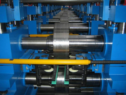
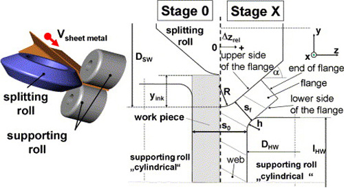
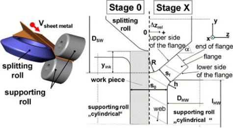
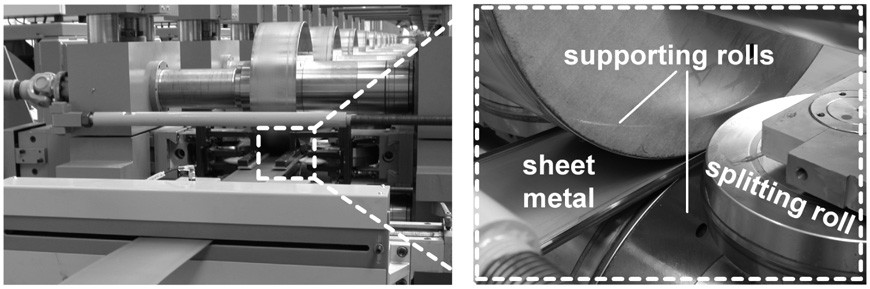
In cooperation with the company Albert Keller Maschinenbau new tool systems were developed and implemented for the linear flow splitting process. This massive forming process allows the production of branched components from metal sheets. For this purpose, a plain metal sheet at room temperature is taken through a tool system, consisting of obtuse splitting rolls and supporting rolls.
The stationary tool system forms the transitionally moved work piece into the desired final geometry. Due to the surface enlargement caused by a flow of the material in the band edges of the metal sheet, branched profiles are formed. The formed linear flow split profile consists of a web and two flanges. The surface facing the splitting roll is defined as the top surface. According to DIN 8580 linear flow splitting is part of the pressure forming processes.
Linear flow splitting stands consist of working shafts with a diameter of 150 mm and a variable center distance to manufacture sheets with up to 4 mm thickness. The initial sheet metal width can be up to 600 mm. With a nominal diameter of 496 mm, the segmented supporting rolls allow variable flange lengths and angles, depending on the chosen incremental infeed and aperture angle.

The splitting rolls have a continuous infeed of up to 300 mm on each side and can be adjusted with an offset of up to 150 mm in traverse direction. By choosing a suitable supporting roll width, the incremental infeed can be selected freely in 0.5 mm steps. Reaction forces occurring at the splitting rolls during the process are detected by DMS shearing bolts.
The drive power of 11.3 kW of each working shaft allows forming speeds of up to 100 m/min. The integrated Simatic-S7 control, made by the company Siemens, allows an independent set up for each drive of upper and lower shaft of the flexible production plant. Each stand can be rearranged independently on the machine base.
Ten linear flow splitting stands are available and allow a continuous production. For a discontinuous production of sheet metal all tool systems have additional side guide rollers.

Technical data
- Max. sheet metal width: 600 mm
- Max. sheet metal thickness: 4 mm
- Working shaft: Ø 150; individual drive
- Supporting roll diameter: 496 mm
- Drive power of working shaft: 11.3 kW