By a defined impact of two joining partners a material closed joint can be realized even between different materials that cannot be welded thermally. However, the industrially used processes are hardly observable, wherefore the joining mechanisms are still not fully understood. While the observability in explosion welding is limited due to the explosives, the joining process in electromagnetic pulse welding is strongly transient.
The model test rig has been developed to be able to investigate the fundamental mechanisms of collision welding with high repeatability. Therefore, an adjustable variation of individual process parameters with otherwise constant test conditions as well as good process observability is the main focus.

Functional principle
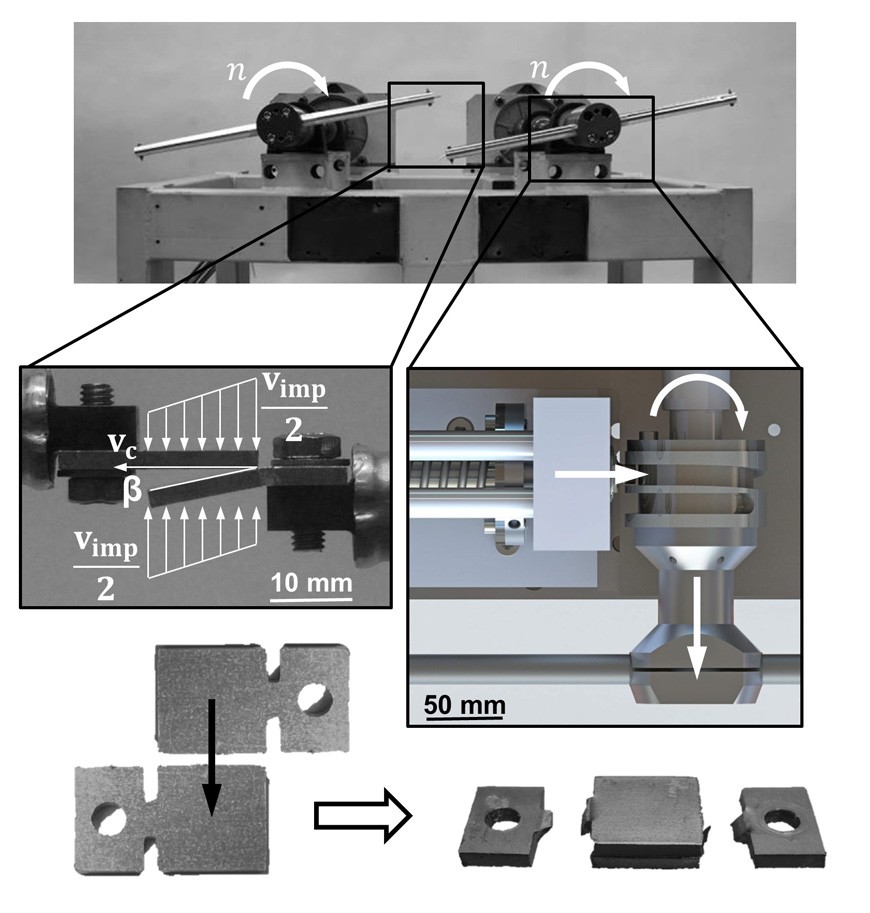
Two specimens are accelerated purely mechanically by two revolving rotors and collide, whereby the welding process is initiated. The rotors initially start with an offset of one specimen width in the axial direction of the drive shaft. The collision is triggered when the desired impact velocity is reached by the insertion of a pretensioned pin into a spiral groove connected to the rotor hub. As a result, the rotor is pushed into the other within one revolution (at 6000 rpm in 10 ms).
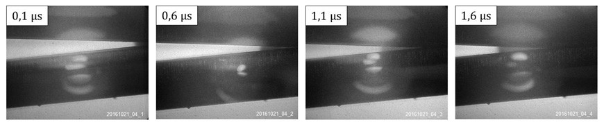
The processes in the collision region are documented by means of high-speed images of an image intensifier camera . A long distance microscope system provides a high local resolution of the area observed, while a pulsed diode laser also ensures adequate illumination and allows imaging under incident as well as transmitted light.

Technical data
- Two controlled synchronous motors
- Drive power: 2 x 12 kW
- Angular deviation: max. 0.1°